
General Information Tab – Zone Name
This identifies the name of the zone. The default name is “Whole House”. If adding additional zones, they should be uniquely named.
Pro Tip: In most applications it is only necessary to model a single zone, even if multiple zones are present.
Conditioned: A zone is modeled as being either conditioned space or unconditioned space. The floor area of an unconditioned zone is not included in the conditioned floor area values calculated by Micropas. The default is “Yes”.
Infiltration: The infiltration unit of measure is expected to be ACH at 50 Pa. If Ekotrope or Rem/Rate use this same unit of measure, then the value will be copied over. If Ekotrope or Rem/Rate designate “CFM at 50 Pa” or “Specific Leakage Area” then the values will be converted to an “ACH at 50 Pa” value.
Floor Area (sqft): Conditioned floor area of the building zone in square feet.
Volume (cuft): The volume of the conditioned space in cubic feet.
Radiant Barrier or Cool Roof: Indicates whether the effect of a radiant barrier or cool roof is being modeled. Micropas models the tempering effects of radiant barriers or a cool roof on both the attic temperature and the surface temperature of ducts in the attic.
Verified Insulation Quality (insulation grade): Credit is given when the quality of insulation installation will be significantly improved to eliminate gaps, sagging and compression.
Bedrooms: Number of bedrooms.
Mechanical Tab – Heating
Enter the heating type and efficiency (e.g., AFUE = 0.96, HSPF = 10.0). If imported from Ekotrope or REM/Rate the type and efficiency is copied over. It is highly recommended that the imported values be confirmed and edited if incorrect.
Heating Types:
- Electric: For electric heating systems other than heat pumps.
- Floor: For gas floor furnaces. Minimum efficiency is based on capacity.
- Furnace: For gas or oil fired furnaces, or heating equipment which is considered equivalent to gas furnaces. Propane and natural gas are treated the same.
- HPGas: For gas-fired heat pumps.
- HPPackage: For packaged heat pump heating systems.
- HPSplit: For split-system heat pump heating systems.
- Hydronic: Micropas does not allow for running a plan with hydronic heating. Please select Furnace.
- Room: For gas room heaters. Minimum efficiency is based on capacity.
- RoomHP: For a room heat pump.
- RoomHPSL: For a room heat pump with side louvers.
- Wall: For gravity type gas wall furnaces. Minimum efficiency is based on capacity.
- WallFan: For fan type gas wall furnaces. Minimum efficiency is based on capacity.
- Wood: For areas without natural gas, a wood heating system with any backup is modeled as a 78% AFUE central gas furnace.
Cooling
Enter the cooling type and SEER (e.g., SEER = 15). If imported from Ekotrope or REM/Rate the type and efficiency is copied over. It is highly recommended that the imported values be confirmed and edited if incorrect.
Cooling Types:
- ACPackage: For packaged air conditioning systems.
- ACSplit: For split air conditioning systems.
- Evaporative: Use only with evaporative cooling. Use an SEER of 11 for direct evaporative cooling, which uses direct contact with water to cool a building or room. Use an SEER of 13 for indirect (also known as indirect/direct) evaporative cooling, which uses a first-stage heat exchanger to pre-cool air and a second-stage with direct contact with water.
- GasAbsorption: For gas-fired absorption cooling equipment.
- HPPackage: For packaged heat-pump cooling systems. Minimum value is 13.0 SEER.
- HPSplit: For split heat pump cooling systems. Minimum value is 13.0 SEER.
- NoCooling: Sets the standard budget cooling system to 13.0 SEER. Use when no cooling system is installed.
- RoomAC: For room air conditioners. Minimum efficiency is based on capacity.
- RoomACSL: For room air conditioners with side louvers. Minimum efficiency is based on capacity.
- RoomHP: For room heat pumps. Minimum efficiency is based on capacity.
- RoomHPSL: For room heat pumps. Minimum efficiency is based on capacity.
Ducts
Micropas requires inputs for the location of “heating” ducts and “cooling” ducts. Ducts are normally shared between the heating and cooling systems. However, these separate input values allow for scenarios where ducts may not be used in certain situations such as a building heated with electric baseboard heaters (no ducts) and cooled with a central air conditioner (with ducts).
If imported from Ekotrope or REM/Rate the distribution system will be copied over. Confirm imported values.
Verified leakage
Enter the duct leakage factor based on results from the duct test. The duct leakage factor is calculated from the measured CFM leakage divided by the sqft of the conditioned floor area served by the cooling equipment (e.g., 90 cfm leakage / 1500 sqft = 0.06).
When imported from Ekotrope or REM/Rate the verified leakage factor is calculated based on the Leakage To Outside (CFM@25Pa) divided by the Square feet served for the distribution system (Leakage = CFM/CFA). In the case where there is more than one distribution system the worst-case calculated value is used.
Conditioned duct sizing & insulation
Conditioned duct sizing & insulation is only required when a section of duct is within a conditioned space.
- Location: Indicate the majority location of the duct. This location will match the heating and cooling duct location.
- Length (ft): Indicate the length of supply duct.
- Diameter (in): Input the diameter of the supply duct. Legal values are 6, 8 12, 16 or other user entered values.
- R-Value: The insulation R-value applied to the duct. Legal values are 4.2, 6 or 8 or other user entered values.
When a distribution system with ducts in conditioned space is imported from Ekotrope or REM/Rate a reasonable best guess duct length is automatically calculated based on the Supply Duct Area with an assumed duct diameter of 12 inches. Check and edit values as necessary.
Duct Length = Supply Duct Area / [(2 x ) x (Duct radius/12)]
Duct Location Options:
- 12InAttic : Use this keyword when the main air handler and all but 12 linear feet or less of ducts and plenums are located within the conditioned space, with the remaining 12 feet or less located in the attic. The length of a plenum is the cross diagonal measurement of the box.
- 12InBasement : Use this keyword when the main air handler and all but 12 linear feet or less of ducts and plenums are located within the conditioned space, with the remaining 12 feet or less located in the basement. The length of a plenum is the cross diagonal measurement of the box.
- 12InCrawlspace : Use this keyword when the main air handler and all but 12 linear feet or less of ducts and plenums are located within the conditioned space, with the remaining 12 feet or less located in the crawlspace. The length of a plenum is the cross diagonal measurement of the box.
- 12InGarage : Use this keyword when the main air handler and all but 12 linear feet or less of ducts and plenums are located within the conditioned space, with the remaining 12 feet or less located in the garage.
- 12InOther : Use this keyword when the main air handler and all but 12 linear feet or less of ducts and plenums are located inside the conditioned space, with the remaining ducts located in some other location. The length of a plenum is the cross diagonal measurement of the box.
- Attic : Use this keyword when the majority of duct work is located in the attic. This is the default duct location. This assumption is also modeled for No Cooling Installed and Evaporative Cooling.
- Combination : Use this keyword when the supply ducts are in multiple locations. Use SUPPLY DUCT SYSTEMS to input details about the locations and conditions of the supply ducts.
- Other : Use this keyword when the majority of ductwork is located in a location that does not fit the description of any other keyword.
- None : Use this keyword only when the heating system does not use ducts (e.g. for a wall-furnace or through-the-wall heat pump). For evaporative cooling or no cooling, see Attic.
- Garage : Use this keyword only when all ducts are located in a garage or open space.
- CVCrawlspace : Use this keyword only when all ducts are located in a controlled ventilation crawlspace (see Chapter 3, Advanced Topics, for details on how to model controlled ventilated crawlspaces).
- Crawlspace : Use this keyword when all supply registers are in the floor and the majority of duct work is located in the crawlspace.
- Conditioned : This keyword may only be used when all ducts and plenums are located in conditioned space, otherwise model keyword ’12In…’ which assume that all but 12 feet of the ducts and plenums are inside conditioned space. The supply duct systems section must be completed when using this keyword.
- Basement : Use this keyword when all supply registers are in the floor and the majority of duct work is located in the basement. This value that Micropas uses for this keyword is identical to ducts in the Crawlspace.
Fan
Micropas fan ventilation is only required when the infiltration falls below a minimum value of 3 SLA.
Walls Tab
“Adiabatic walls, ceilings & floors are not imported from XMLs and can be omitted in Micropas.”
Type : Select the wall construction type from the drop down list. Adding, removing or editing wall construction types can be done from the components library.
Area (sqft) : Enter the surface area of the wall in square feet.
Azimuth : Select the Azimuth (orientation) of the wall with respect to the primary entrance of the building (front facade). Legal values are ‘Front’, ‘Left’, ‘Back’ and ‘Right’.
Solar Gains : Select “Yes” or “No” depending on whether or not the sun strikes the wall. This value should be set to ‘No’ for walls adjacent to garages and other shaded walls.
Fenestration : Select Type and Overhangs from dropdown lists (which reference the Components) and enter the total area
Wall Splits : In Micropas, the areas of walls, windows, doors, and ceilings can be grouped according to their orientation and U-factor. Solar gains are assumed for these constructions unless their exterior surface is substantially shaded by the building structure. Orientation and solar gain can therefore play an important role in calculating the energy budget. On import wall types to exterior, those with solar gains, are split out into four orientations. These should be carefully reviewed and updated as needed.
An advantage Micropas has over other software is its ability to calculate energy budgets based on orientation of walls. Since most modelers create a single wall to ambience regardless of the orientation, on import, wall types to exterior (solar gains) are split out into four orientations. Let’s say we have two”Above Grade Wall” types:
- R15 2×4 (to exterior) = 200 sqft
- R15 2×4 Garage (to garage) = 30 sqft
On import the R15 2×4 wall to exterior will be split out to front, left, back and right. The auto split assumes a wall to garage is facing front and will reduce the amount of wall to exterior and add the difference back to the Back, Left and Right walls.
For example, for the wall to exterior of 200 sqft, 200/4=50 so each azimuth would get 50 sqft for F, L, B and Right. But because there is a garage = 30 sqft. The Front wall to exterior is reduced by 30 sqft with a final assignment of Front = 20 sqft. The remaining 30 sqft that was displaced is divided by 3 (30/3=10) and added back to Left, back and right. So Left, Back and Right = 50 + 10 = 60 sqft respectively.
- R15 2×4, Front = 20 sqft
- R15 2×4, Left = 60 sqft
- R15 2×4, Back = 60 sqft
- R15 2×4, Right = 60 sqft
- R15 2×4 Garage, Front = 30 sqft
The wall areas should be edited as needed, as long as the sqft should add up to what was originally modeled before Import. 200 sqft for the wall to exterior and 30 sqft for wall to garage. The more accurate the split the more accurate the calculated budget.
Important: Note that is the original modeler did break out the exterior walls by orientation, CHEERS 45L will unnecessarily duplicate these walls. In this case simply delete the walls that do not exist.
Window Replacements
The Ekotrope and REM/Rate files provide the orientation and wall assignment for each window or glass door. On import, this information is used to place each window or glass door to its assigned wall based on its original orientation (e.g., North, East, South, West).
For example, if the let us say on import the building front or “Front facing” was specified as “East” (Front = East). Let’s also say we have two windows; Window 1 faces South and Window 2 faces West and both are assigned to Wall Type 1.
On import Wall Type 1 is to exterior and is split out to Front (East), Left (South), Back (West) and Right (North). In this scenario Window 1 will be placed on Wall Type 1 the Left wall and Window 2 will be placed on the Back wall.
Foundation Walls Tab
Enter foundation wall thickness, area, insulation R-Value and Depth Below Grade information. Imported data from Ekotrope and REM/Rate are copied over.
Foundation Wall Fenestration
Coming Soon!
Roofs/Ceilings Tab – Fenestration (Skylights)
Coming Soon!
Doors Tab
Coming Soon!
Framed Floors Tab
Coming Soon!
Slabs Tab
Type : Choose the Appropriate floor grade type, “Below Grade” or “On Grade”. If importing from Ekotrope or RemRate the floor grade type will be determined, and the type assigned. Edit, if necessary.
Thickness (inches) : Enter the slab thickness in inches. If importing from Ekotrope or REM/Rate a default value of 4 inches will be assumed. Edit, if necessary.
Area (square feet) : Enter the exterior surface area of the slab. If importing from Ekotrope or REM/Rate the surface area value will be imported.
Perimeter (linear feet) : Enter the exposed perimeter in linear feet. If not applicable enter “0”. If importing from Ekotrope or REM/Rate the exposed perimeter value will be imported.
Insulation R-Value : Enter the perimeter insulation R-Value. If not applicable enter “0”. If importing from Ekotrope or REM/Rate the perimeter insulation R-Value will be imported.
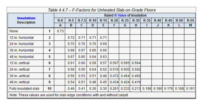
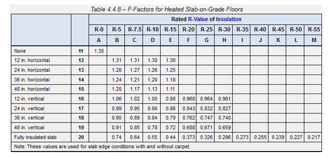
Insulation F-Factor : Enter the insulation F-Factor based on the look up value for either an unheated or heated slab. For example, an un-heated slab with R-10 insulation at a vertical depth of 2 ft will have an F-Factor value of 0.54.
If importing from Ekotrope or REM/Rate the F-Factor will be determined based on the perimeter insulation R-Value, perimeter insulation depth and radiant slab value. Edit, if necessary.